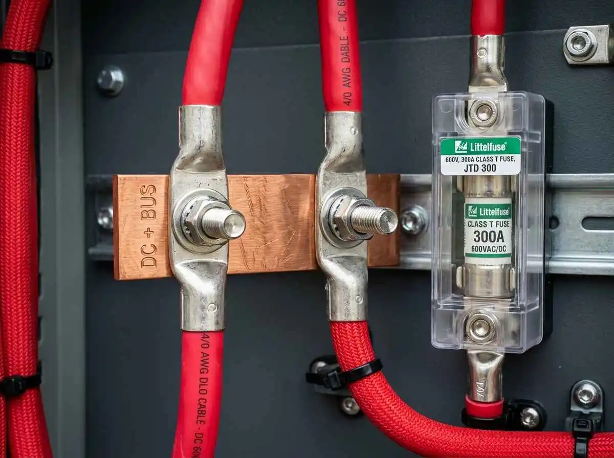
When building a high-capacity 48V lithium iron phosphate (LiFePO4) energy storage system, mechanical connections and overcurrent protective devices (OCPD) are frequently treated as afterthoughts. Homeowners often spend thousands on server-rack battery modules and hybrid inverters, only to bottleneck the system with undersized copper bars or dangerous, slow-blow automotive fuses.
A dead short on a 48V, 300Ah+ lithium bank can discharge upwards of 10,000 to 20,000 amps in milliseconds. Without proper busbar cross-sectional sizing and high-interrupt-capacity fusing, copper will vaporize, busbars will warp, and the resulting arc flash presents catastrophic fire and life-safety hazards.
Here is the exact engineering criteria to properly size central combiner busbars and select between Class T, ANL, and Mega fuses for residential energy storage.
Busbar Ampacity and Cross-Sectional Area Calculations
A central busbar combines multiple parallel battery banks and delivers low-resistance power to the inverter. To prevent dangerous thermal buildup inside your battery enclosure, busbars must be sized based on continuous current ratings plus safety continuous-duty margins mandated by electrical codes.
Formula for Cross-Sectional Area:
Standard electrical-grade copper (CDA 110 alloy) possesses a conductivity rating of roughly 1,000 to 1,200 amps per square inch of cross-sectional area for safe indoor enclosure installations without forced cooling.
Cross-Sectional Area (sq in) = Thickness (in) × Width (in)
Continuous Ampacity Rating = Area (sq in) × 1,000 A/sq in
Standard Solid Copper Bar Dimensions & Safe Ampacity Ratings:
| Dimensions (Thickness × Width) | Cross-Sectional Area | Continuous Rated Ampacity (CDA 110) | Max Inverter Continuous Output (48V) |
|---|---|---|---|
| 1/8″ × 1″ (3.2 mm × 25.4 mm) | 0.125 sq in | ~125A – 150A | 6,000W continuous |
| 1/4″ × 1″ (6.35 mm × 25.4 mm) | 0.250 sq in | ~250A – 300A | 12,000W continuous |
| 1/4″ × 1.5″ (6.35 mm × 38.1 mm) | 0.375 sq in | ~375A – 450A | 18,000W continuous |
| 1/4″ × 2″ (6.35 mm × 50.8 mm) | 0.500 sq in | ~500A – 600A | 24,000W+ (Commercial / Parallel Inverters) |
The Interrupt Rating Debate: Class T vs ANL Fuses
The single most dangerous misconception in DIY solar storage is assuming that an automotive-grade ANL fuse is adequate for a primary lithium DC bus. While an ANL fuse may share the same continuous amp rating (e.g., 300A) as a Class T fuse, their Ampere Interrupting Capacity (AIC) differs by orders of magnitude.
- Ampere Interrupting Capacity (AIC): The maximum fault current a protective device can safely interrupt without disintegrating, arcing over, or catching fire.
Technical Breakdown: Class T vs ANL
| Specification | Class T Fuse | ANL Fuse |
|---|---|---|
| Interrupt Rating (AIC @ DC) | 20,000A to 50,000A DC | 2,000A to 6,000A DC (Often unrated for DC) |
| Clearing Speed | Extremely Fast-Acting (Sub-cycle clearing) | Slow to Medium blow profile |
| Arc Flash Suppression | Sealed industrial ceramic tube with silica quartz sand quenching | Open plastic/phenolic window (Prone to internal plasma burn) |
| Cost & Availability | Higher initial investment ($40 – $75 with holder) | Budget-friendly ($10 – $20) |
| Suitability | Mandatory for modern LiFePO4 packs | Legacy low-draw lead-acid or marine 12V trolling systems |
Because LiFePO4 chemistry features near-zero internal resistance (as detailed in our analysis of LiFePO4 vs Lead-Acid for home backup), short-circuit currents surge exponentially faster than lead-acid banks. If an ANL fuse experiences a direct fault on a multi-battery 48V bank, the extreme energy can blow the fuse element, ionize the surrounding air, and sustain an electric arc across the terminal posts—continuing to pump energy into the short. Always install a Class T fuse on the primary positive bus.
Sizing Your Main DC Fuse: The 125% NEC Rule
Per NEC Article 240.4 and Article 706 (Energy Storage Systems), overcurrent protection must be rated for at least 125% of the continuous operating current to prevent nuisance tripping under sustained load.
Formula:
Continuous Current (Amps) = Inverter Continuous Output (Watts) / Minimum Operating Battery Voltage (V)
Fuse Rating (Amps) = Continuous Current × 1.25
Practical Sizing Example:
Assume an off-grid installation running a 6,000W (6 kW) split-phase inverter backed by a 48V bank configured according to our 48V LiFePO4 sizing guide:
- Inverter continuous wattage: 6,000W
- Inverter efficiency: ~92% (Total battery draw = 6,000W / 0.92 = 6,521W)
- Cut-off battery voltage under load: 44V DC
- Maximum continuous current:
6,521W / 44V = 148.2A - Continuous calculation factor:
148.2A × 1.25 = 185.25A
Result: Select the next standard fuse size up: a 200A Class T fuse paired with copper cable sized to match (e.g., 2/0 AWG with 90°C insulation rating). Sizing the fuse larger than the cable’s thermal rating violates safety codes.
Best Practices for Busbar and Terminal Assembly
- Torque to Manufacturer Specifications: Loose mechanical joints cause localized resistive heating. Always use a calibrated torque wrench on battery terminals and busbar studs (typically 8 to 10 Nm for M8 hardware).
- Proper Terminal Stacking Order: When mounting heavy-gauge lug terminals to busbars, the lug must sit flat against the copper bar, followed by a flat washer, a Belleville/spring lock washer, and the securing nut. Never place a washer between the conductor lug and the busbar face.
- Non-Conductive Enclosures: Enclose all raw copper busbars in protective poly-carbonate or acrylic covers to eliminate accidental short circuits caused by dropped tools during maintenance.
Summary
Reliable energy storage depends on clean, safe physical connections. Sizing solid CDA 110 copper busbars to accommodate peak current draws and installing an industrial fast-acting Class T fuse ensures your critical circuits—audited per our home energy audit guide—remain safely powered without risking catastrophic thermal runaway.