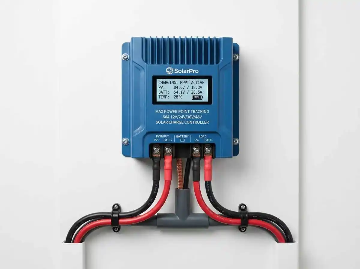
Selecting an undersized Maximum Power Point Tracking (MPPT) charge controller bottlenecks your entire solar array, leaving valuable energy unharvested on peak sunny days. Conversely, selecting an oversized controller needlessly drains your budget on unused current capacity. Worse still, miscalculating maximum input voltage risks catastrophic electronic failure the first time winter temperatures drop.
Unlike legacy Pulse Width Modulation (PWM) controllers—which drag solar panel voltage down to nominal battery voltage and discard the surplus as wasted heat—an MPPT controller functions as a high-frequency DC-to-DC buck converter. It transforms high-voltage, low-current PV power into precisely regulated low-voltage, high-current power tailored to your battery’s absorption profile.
Here is the precise engineering math, current sizing formulas, and thermal safety calculations required to size an MPPT charge controller for a 48V residential battery backup system.
The Core MPPT Sizing Formula: Output Amperage
Charge controllers are rated by two primary metrics: Maximum Array Input Voltage ($V_{max}$) and Maximum Continuous Output Current (Amps). While input voltage dictates panel string configuration, output current dictates how fast energy can physically enter your battery bank.
Formula for Output Current:
Rated Output Amps = Total Array Wattage (W) / Minimum Battery Charging Voltage (V)A frequent DIY mistake is using the battery’s nominal voltage (48V) in this formula. As demonstrated in our benchmark guide on LiFePO4 vs Lead-Acid for home backup, a 48V lithium iron phosphate bank absorbs bulk charge between 54.4V and 56.8V, whereas depleted lead-acid banks drop to ~44V.
To ensure a conservative safety margin that avoids constant controller thermal throttling, standard engineering practices use the nominal 48V to 50V baseline when calculating output current.
Real-World Sizing Example:
Suppose you install ten 400W monocrystalline solar panels totaling 4,000W (4 kW):
- Total PV Array Output: 4,000 Watts
- Nominal Charging Voltage: 48 Volts DC
- Required Controller Amperage:
4,000W / 48V = 83.3 Amps
Result: An 80A controller would operate at continuous maximum thermal saturation on clear summer afternoons. The correct selection is a standard 100A MPPT controller or two 50A controllers operating in parallel sharing a synchronized communication bus.
Quick MPPT Sizing Reference Table (48V LiFePO4 Systems)
| Total Solar Array (Watts) | Nominal Battery Voltage | Theoretical Current | Recommended MPPT Controller Rating | Max Recommended Continuous PV Input |
|---|---|---|---|---|
| 1,200W | 48V (51.2V nom) | ~24A | 30A MPPT | 1,500W (125% Over-panneled) |
| 2,400W | 48V (51.2V nom) | ~48A | 60A MPPT | 3,000W (125% Over-panneled) |
| 3,600W | 48V (51.2V nom) | ~72A | 80A – 85A MPPT | 4,500W (125% Over-panneled) |
| 4,800W | 48V (51.2V nom) | ~96A | 100A MPPT | 6,000W (125% Over-panneled) |
The Concept of Over-Paneling: Why 120% to 130% is Optimal
Over-paneling refers to connecting a solar array whose peak STC wattage exceeds the controller’s maximum continuous output rating. High-grade MPPT charge controllers (such as Victron SmartSolar or Schneider Conext) automatically clip excess incoming amperage by adjusting internal switching duty cycles, preventing electronic damage as long as input voltage limits are not breached.
Benefits of Intentional Over-Paneling:
- Flattens the Production Curve: Peak STC ratings assume laboratory conditions (1,000 W/m² irradiance, 25°C cell temp). Under real-world heat, panels typically produce 15% to 20% below nameplate. An oversizing ratio of 1.25x enables the controller to reach full rated output earlier in the morning and maintain it later into the evening.
- Superior Winter & Overcast Performance: When heavy cloud cover reduces array irradiance by 70%, an over-paneled array still pushes meaningful current to critical loads audited per our home energy audit guide.
Input Voltage Matching & Temperature Correction (The Hard Limit)
While an MPPT controller safely clamps excess current, it cannot protect itself against excess voltage. Exceeding the controller’s Maximum Open-Circuit Voltage ($V_{oc}$) rating—even for a split second—destroys internal MOSFET transistors and voids warranties instantly.
As covered in our guide on DIY solar panel wiring (series vs parallel), open-circuit voltage rises as ambient temperatures drop below 25°C (77°F).
Safety Protocol for Inverter Voltage Input:
- Determine the lowest historical ambient temperature recorded in your geographical area.
- Multiply the panel string’s combined STC $V_{oc}$ by the temperature coefficient delta.
- Maintain a 10% to 15% Engineering Headroom: If your MPPT controller has a 150V limit, the temperature-corrected string voltage must never exceed 135V to 140V DC under any weather scenario.
Wiring, Fusing, and Busbar Integration
A 100A continuous charging current represents substantial thermal loading. Per NEC Article 690 and 706, output conductors running from the MPPT controller to your central battery busbar must be sized for 125% of maximum continuous output:
- Conductor Gauge: For a 100A controller, calculate
100A × 1.25 = 125Aminimum ampacity. Use minimum 2 AWG or 1/0 AWG fine-stranded copper wire with 90°C rated insulation. - Overcurrent Protection: Install a high-interrupt capacity fuse directly adjacent to the busbar. Review our comprehensive breakdown on busbar sizing and Class T vs ANL fuses to prevent arcing faults between your controller and high-capacity lithium storage.
Summary
Accurate MPPT controller sizing requires balancing continuous output amperage against your daily consumption profile while strictly obeying open-circuit voltage ceilings during freezing conditions. By pairing temperature-corrected high-voltage series strings with a 120% to 125% over-paneled array, you ensure your 48V battery bank receives smooth, uninterrupted charging throughout every season.