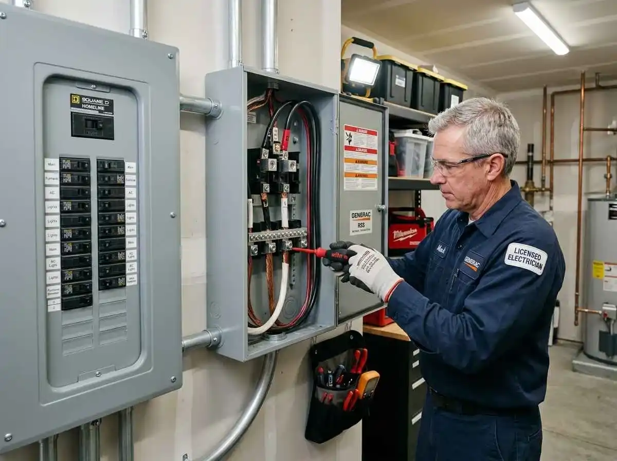
Connecting a multi-kilowatt battery inverter directly to your home’s electrical distribution without a physical isolation mechanism is both illegal and lethal. During a utility grid failure, energized residential circuits will backfeed power onto external neighborhood power lines, turning localized distribution transformers into step-up hazards that endanger utility linemen working down the street.
To safely isolate your home while routing stored energy to critical circuits, an electrical transfer switch is mandatory. Homeowners must choose between a budget-friendly Manual Transfer Switch (MTS) and a seamless Automatic Transfer Switch (ATS), while calculating proper continuous bus ampacity per National Electrical Code standards.
Here is the practical engineering guide for selecting, sizing, and installing a transfer switch for modern residential battery storage systems.
Manual vs Automatic Transfer Switches: Architectural Differences
A transfer switch prevents utility grid lines and off-grid inverter outputs from ever making simultaneous contact. It uses mechanical interlocks, contactor coils, or motorized cams to guarantee break-before-make circuit isolation.
| Feature | Manual Transfer Switch (MTS) | Automatic Transfer Switch (ATS) |
|---|---|---|
| Transfer Time | Manual (Minutes, requires human presence) | Instantaneous to Sub-Cycle (10ms to 30ms) |
| Hardware Cost | Low ($150 – $450) | Moderate to High ($500 – $1,800+) |
| Installation Complexity | Simple multi-circuit whip or interlock plate | Advanced (Requires control signal wiring, coil relays, and sensing lines) |
| Computer / Medical Power Drop | Complete power loss until switched manually | Zero disruption (Hybrid inverters maintain UPS transfer speeds) |
| Ideal Application | Budget DIY setups, portable power stations, secondary cabins | Unattended homes, critical medical equipment, automated solar setups |
Sizing the Transfer Switch: Ampacity and Poles
Selecting the correct transfer switch requires matching both the continuous amperage rating and the physical phasing of your incoming service panel.
1. Single-Phase vs Split-Phase (Poles)
Standard North American homes utilize 120V/240V split-phase power consisting of two ungrounded hot legs (Line 1 and Line 2), a neutral conductor, and an equipment ground. To power 240V well pumps, electric dryers, or balanced 120V subpanels, your transfer switch must feature two switching poles (Double-Pole).
2. Switched Neutral vs Solid Neutral (3-Pole vs 2-Pole)
Whether your neutral wire is switched dictates how your system interacts with system grounding:
- Solid (Unswitched) Neutral: Used when your battery inverter does not have an internal neutral-ground bond while operating. The home’s main service panel remains the single source of bonding, compliant with NEC Article 250.
- Switched Neutral (Separately Derived System): Required if your hybrid inverter or backup generator features a permanently bonded neutral internally. Failing to switch the neutral in this configuration creates parallel ground paths, nuisance tripping on GFCI/AFCI breakers, and stray neutral currents.
Calculating Ampacity: Whole-Home vs Critical Load Subpanel
Transfer switches are generally rated at 30A, 50A, 100A, or 200A continuous duty.
Option A: 200A Whole-Service Disconnect
An ATS rated at 200A is installed between the utility electric meter and the main distribution panel. While this allows every circuit in the house to receive backup power, your battery bank must be massive enough to prevent instantaneous low-voltage shutdown if heavy inductive loads start simultaneously.
Option B: 50A to 100A Critical Load Transfer Switch (Recommended)
Instead of switching the entire house, an auxiliary transfer subpanel feeds only essential circuits. In our operational guide on conducting a home energy audit and sizing critical load panels, we showed how capping continuous draw at 4,000W to 6,000W reduces initial battery capital costs by over 60%.
To size a critical load transfer switch for a standard 6 kW hybrid inverter operating on a 48V LiFePO4 battery bank:
Maximum Continuous Inverter AC Output = 6,000 Watts
Inverter Continuous Amps @ 240V = 6,000W / 240V = 25 Amps
NEC 125% Continuous Duty Factor = 25A × 1.25 = 31.25 Amps
Result: A 50A double-pole transfer switch provides the optimal thermal headroom, accommodating continuous 120V/240V output alongside brief inductive surge spikes.
Wiring Safety and NEC Code Compliance
When installing transfer switching equipment, verify adherence to the following life-safety standards:
- Mechanical Interlock Mandate (NEC Article 702.6): All transfer equipment must utilize an approved mechanical interlock or factory-assembled contactor design that prevents parallel grid interconnect without explicit utility approval.
- Conductor Ampacity & Protection: All feeders connecting your hybrid inverter’s AC output terminals to the transfer switch must match overcurrent protection ratings. Refer to our detailed guide on busbar sizing and fuse selection to ensure upstream DC circuits remain protected during heavy AC transfer switching.
- Solar Array Synchronization: When paired with an automatic switch, ensure your photovoltaic charge controller smoothly ramps down if the battery reaches 100% absorption while off-grid. Review our math for sizing MPPT charge controllers and over-paneling limits to prevent bus voltage spikes during sudden load disconnects.
Summary
A properly sized double-pole transfer switch converts an isolated lithium battery bank into a secure, code-compliant home emergency power system. For most residential configurations, pairing a 50A or 100A subpanel with an automatic transfer switch provides uninterrupted backup protection for essentials without the expense of whole-house utility disconnects.