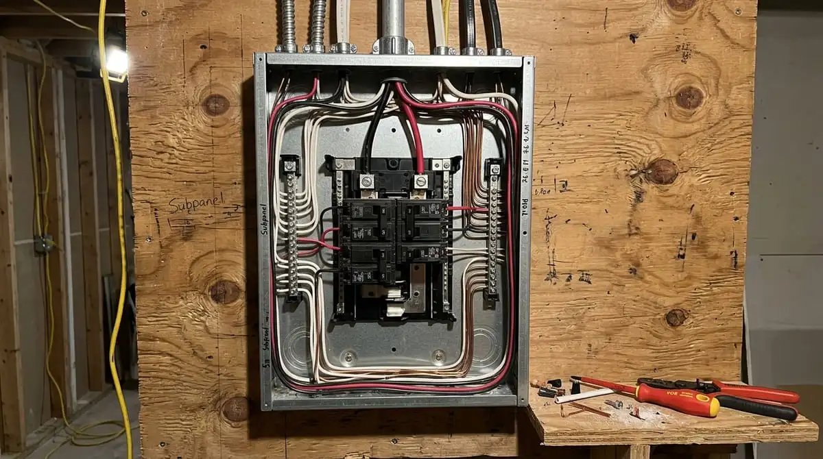
Critical Loads Subpanel Wiring: Neutral-Ground Bonding & NEC 250 Guide
Feeding a dedicated critical loads subpanel from a hybrid inverter looks simple on paper until an unintended second neutral-ground bond trips upstream GFCI breakers, electrifies metal conduits, or destroys sensitive electronics. Creating an accidental parallel return path between your main electrical service panel and your backup panel is the most common mistake made in DIY energy storage installations.
The National Electrical Code (NEC) strictly prohibits bonding neutral to ground downstream of your main service disconnect. Getting this wiring right protects your equipment, keeps the battery management system from nuisance trips, and prevents lethal touch-potential voltages across your home’s grounding electrode system.
The Core Hazard: Multiple Neutral-Ground Bonds and Ground Loops
Under normal conditions, alternating current travels out through the ungrounded “hot” conductors (L1 and L2) and returns through the grounded neutral conductor. Bonding neutral to the equipment grounding conductor (EGC) in more than one location creates two parallel paths for normal return current.
Part of that return current will continuously ride through your equipment ground wires, metal conduit runs, and the metal chassis of your inverter. This stray current generates electromagnetic interference, corrodes copper junctions, defeats Arc-Fault (AFCI) and Ground-Fault (GFCI) protection, and presents a shock hazard whenever you touch equipment enclosures.
WRONG (Objectionable Ground Current):
[Main Panel (Bonded)] === Neutral Line ===> [Subpanel (Bonded)]
                  \\=== Ground Wire ===//
         (Current splits across ground wire and metal chassis)

RIGHT (Single Main System Bond):
[Main Panel (Bonded)] === Neutral Line ===> [Subpanel (Isolated)]
                  \==== Ground Wire =====> [Subpanel Ground Bar]
         (All neutral current returns strictly on the neutral wire)
Step-by-Step Technical Guide: Wiring the Subpanel
Step 1: Remove the Subpanel Bonding Screw or Strap
Open your new critical loads subpanel and locate the green bonding screw or metal bonding strap connecting the neutral busbar to the steel enclosure. Unscrew and discard it, or secure it in the panel’s spare holder so it cannot touch the metal backplate.
Use a digital multimeter set to continuity to confirm total electrical isolation between the neutral busbar and the metal chassis. If your meter beeps when touching one probe to the neutral bar and the other to bare panel steel, your neutral is still bonded.
Step 2: Establish an Isolated Equipment Grounding Bar
Install a dedicated, factory-listed grounding terminal bar kit directly onto the metal enclosure of the subpanel. Scrap away paint beneath the mounting screws if necessary to guarantee a low-impedance bond to the steel enclosure.
All bare copper grounds and green insulated Equipment Grounding Conductors (EGC) from your critical load branch circuits must terminate here. Never terminate a bare grounding wire onto the neutral busbar inside a subpanel.
Step 3: Run Split-Phase Feeders from the Inverter AC Output
Run four conductors from your hybrid inverter’s AC Load/Critical Output terminals into the subpanel: Line 1 (Black), Line 2 (Red), Neutral (White), and Ground (Green or Bare Copper).
Use the table below to select correct conductor ampacity and conduit types per NEC Article 310:
| Inverter Continuous Output | Line Conductors (L1 / L2) | Neutral Conductor | Minimum Equipment Ground (EGC) | Min. EMT Conduit Trade Size |
| 5.0 kW (20.8A @ 240V) | 10 AWG Copper (30A breaker) | 10 AWG Copper | 10 AWG Copper | 1/2 inch |
| 8.0 kW (33.3A @ 240V) | 8 AWG Copper (40A breaker) | 8 AWG Copper | 10 AWG Copper | 3/4 inch |
| 10.0 kW (41.6A @ 240V) | 6 AWG Copper (50A breaker) | 6 AWG Copper | 10 AWG Copper | 3/4 inch |
| 12.0 kW (50.0A @ 240V) | 4 AWG Copper (60A breaker) | 4 AWG Copper | 8 AWG Copper | 1 inch |
| 15.0 kW (62.5A @ 240V) | 2 AWG Copper (80A breaker) | 2 AWG Copper | 6 AWG Copper | 1 inch |
Step 4: Transfer Critical Branch Circuits
De-energize the main service panel before moving selected branch circuits (such as your refrigerator, internet cabinet, and well pump). Pull the hot conductors and their corresponding neutral wires out of the main panel and route them through conduit or Romex into the critical loads subpanel.
Every 120V branch circuit moved into the subpanel must have its dedicated neutral wire moved as well. Sharing a neutral wire between a circuit on the main panel and a circuit on the subpanel creates an unbalanced multi-wire branch circuit (MWBC) hazard that will trip your inverter or destroy appliances.
Hybrid Inverter Dynamic Grounding: Separately Derived vs. Non-Separately Derived
A critical loads subpanel behaves differently depending on whether your hybrid inverter contains an internal automatic bonding relay.
+-----------------------------------------------------------------------------------------+
|                                HYBRID INVERTER ARCHITECTURE                             |
|                                                                                         |
|  [Grid Mode: Pass-Through]                                                              |
|   Main Service Panel (Single N-G Bond) ---> Inverter Internal Relay OPEN                |
|   Neutral passes through; Subpanel relies on Main Panel for safety bonding.             |
|                                                                                         |
|  [Island/Off-Grid Mode: Blackout]                                                       |
|   Inverter Disconnects from Grid ---> Inverter Internal Relay CLOSES (Dynamic Bond)     |
|   Creates temporary local N-G bond at Inverter to clear branch circuit short circuits.  |
+-----------------------------------------------------------------------------------------+
Non-Separately Derived Systems (Grid-Tied Pass-Through)
When the grid is active, most hybrid inverters act as non-separately derived systems. The internal transfer switch connects the utility neutral directly to the subpanel neutral, and the inverter’s internal bonding relay remains open.
The single system neutral-ground bond established at your utility main service entrance handles fault currents. Under no circumstances should you add an extra bond inside the inverter or the subpanel in this mode.
Separately Derived Systems (Off-Grid Island Mode)
During an outage, the inverter’s internal transfer switch disconnects all utility lines, including the grid input conductors. At that microsecond, the subpanel becomes a “separately derived system” (NEC 250.30).
Modern low-frequency and high-frequency residential inverters feature an automated internal dynamic neutral-ground bond. Once the inverter switches to battery backup mode, an internal relay clicks shut, bonding neutral to ground inside the inverter chassis to give circuit breakers a return path to trip in the event of an electrical short.
Critical DIY Mistakes & NEC Code Rules
1. The Shared Neutral Trap (NEC 300.3(B))
Never leave an appliance neutral conductor on the main panel neutral bar while moving only its hot wire over to the subpanel breaker. All phase conductors, the neutral, and the equipment ground of a single circuit must run within the same cable or raceway.
Separating hot and neutral wires across different steel panels creates inductive heating through magnetic eddy currents in the sheet metal, leading to melted insulation and fire.
2. Sizing the Subpanel Neutral Conductor (NEC 220.61)
Do not downsize the neutral conductor feeding the subpanel from your inverter. In a 120V/240V split-phase home backup system, out-of-balance 120V loads (like running an air fryer on L1 while drawing nothing on L2) send full unbalanced current back through the neutral wire.
Size your neutral conductor to carry 100% of the maximum single-phase rating of your inverter feed.
3. Missing Retaining Clips on Backfed Breakers (NEC 408.36(D))
If you feed your subpanel using a backfed branch breaker rather than dedicated main lugs, you must mechanically secure that breaker in place.
Use a manufacturer-listed screw-down hold-down kit to secure the backfed breaker to the panel interior. This prevents the energized breaker from being accidentally pulled out by hand while under load.
Practical Contractor Safety Checklist
Before flipping breakers and transferring live loads to your new backup subpanel, walk through these baseline commissioning checks:
-
Verify Neutral Isolation: Shut off the feeder breaker, isolate the subpanel, and verify high resistance (infinite ohms) between the subpanel neutral busbar and the grounding bar.
-
Torque Terminal Screws: Use a calibrated torque screwdriver on every circuit breaker lug and busbar screw according to the manufacturer specifications stamped on the panel door (typically 35 to 45 in-lbs for branch terminals).
-
Confirm Inverter Relay Settings: Check your inverter’s digital menu (e.g., Sol-Ark, EG4, Victron) to ensure the internal N-G bond setting matches your system design. It should be configured to “Auto/Dynamic” rather than permanently fixed or disabled.
-
Perform GFCI/AFCI Testing: Once energized on battery power, test all ground-fault and arc-fault breakers within the subpanel using their physical test buttons to confirm they trip instantly under inverted power.