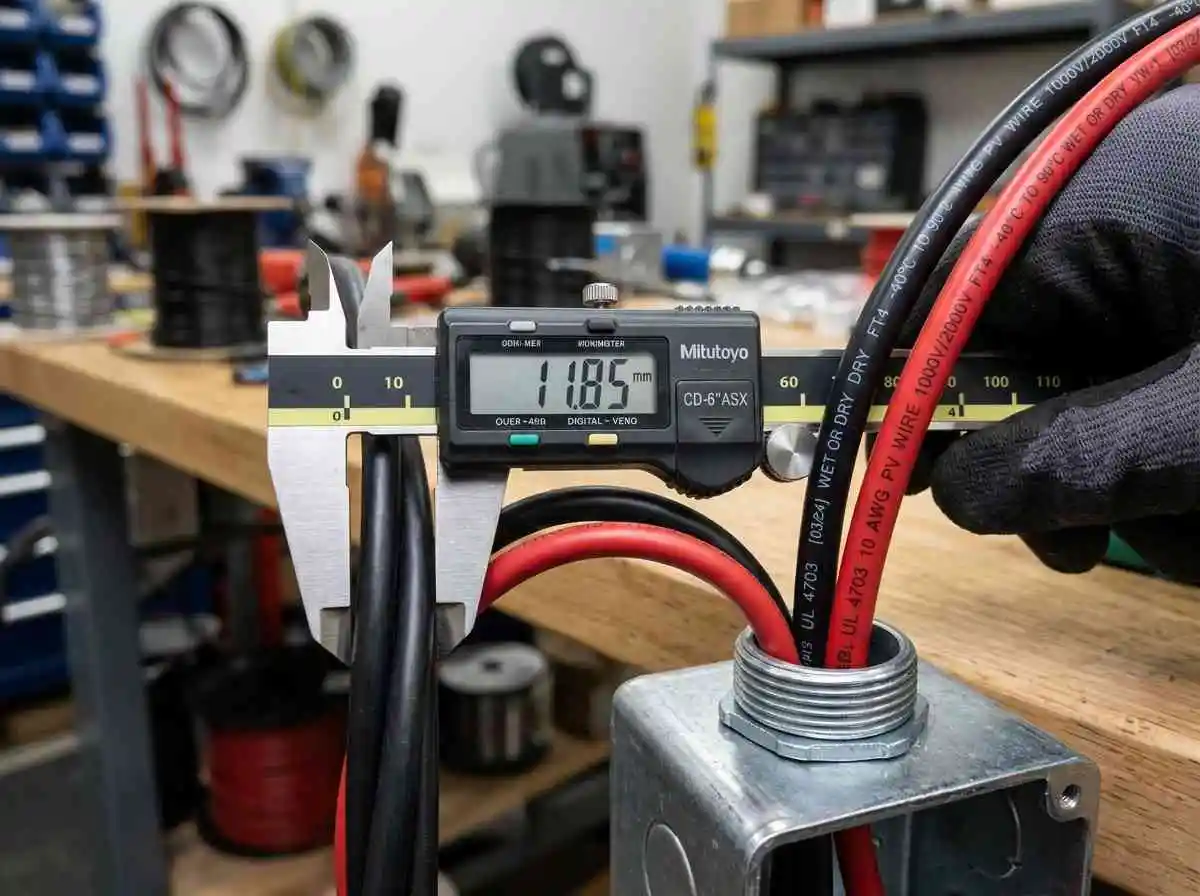
Direct current generated by photovoltaic modules must travel from high-temperature rooftop environments through protective conduit down to balance-of-system power electronics. If conductors are undersized or thermal derating factors are ignored, resistive heat buildup silently dissipates harvestable kilowatt-hours, induces premature insulation failure, and creates severe electrical fire hazards under sustained maximum power point currents.
Sizing photovoltaic conductors requires far more than matching wire gauge to standard nameplate amperage. Because solar arrays operate continuously at peak output for hours under intense solar irradiance, the National Electrical Code (NEC) mandates strict continuous duty multipliers, ambient roof-level temperature corrections, and conduit fill adjustments.
Here is the mathematical framework for calculating conductor ampacity, applying NEC 310 thermal adjustment factors, sizing conduit fill ratios, and limiting DC voltage drop below 2% on residential solar arrays.
PV Wire vs Standard USE-2 / THHN Conductors
When selecting conductors for array interconnections, understand the chemical and thermal distinctions between standard building wire and specialized solar cable:
- Standard THHN / THWN-2: Rated for interior building conduit. Its thin thermoplastic nylon jacket lacks adequate UV stabilization and will rapidly crack if exposed to direct outdoor sunlight.
- USE-2 Cable: Underground Service Entrance cable rated for 90°C wet conditions and outdoor exposure, but restricted to grounded solar arrays.
- UL 4703 Dedicated PV Wire: The modern industry standard. Features thick, cross-linked polyethylene (XLPE) dual-layer insulation rated for 90°C or 105°C wet/dry applications, 600V to 2,000V DC working voltage, superior flame resistance, and full flexibility in sub-zero winter temperatures. Crucially, NEC 690 mandates PV Wire for all modern ungrounded (floating) array architectures.
The Step-by-Step Ampacity Calculation Math
To determine the minimum allowable wire gauge (AWG), follow the sequence defined by NEC Article 690.8 and Article 310.
Step 1: Calculate Maximum Circuit Current ($I_{max}$)
Per NEC 690.8(A)(1), solar module short-circuit current ($I_{sc}$) must be multiplied by a 125% factor to account for edge-of-cloud atmospheric irradiance amplification:
Maximum Circuit Current (Imax) = Array Short-Circuit Current (Isc) × 1.25Step 2: Apply the Continuous Duty Safety Margin
Because solar circuits carry continuous current for three or more consecutive hours, apply an additional 125% factor per NEC 690.8(B)(1):
Minimum Conductor Ampacity = Imax × 1.25 = Array Isc × 1.56If a parallel string configuration generates a combined $I_{sc}$ of 18 Amps:
Minimum Continuous Ampacity Baseline = 18A × 1.56 = 28.08 AmpsThermal Derating Factors (NEC Table 310.15)
A conductor’s current-carrying capacity drops dramatically when heated. Conduits mounted flat across dark asphalt shingle roofs absorb intense radiant heat, frequently reaching ambient internal temperatures well above 50°C (122°F).
Formula for Adjusted Ampacity:
Derated Ampacity = Table Ampacity × Temperature Correction Factor × Conduit Fill FactorPractical Derating Scenario:
Consider 10 AWG Copper PV Wire (rated at 40A under the 90°C column in NEC Table 310.16) routed through roof conduit:
- Design Ambient Roof Temperature: 45°C (113°F).
- Temperature Correction Factor ($C_t$): Per NEC Table 310.15(B)(1), the correction factor for 90°C wire at 45°C ambient is 0.87.
- Conduit Fill Factor ($C_f$): If routing four current-carrying conductors (two parallel strings) through the same pipe, NEC Table 310.15(C)(1) applies an 0.80 adjustment factor.
Calculation:
Real-World Derated Ampacity = 40A × 0.87 × 0.80 = 27.84 AmpsEngineering Verdict: Because 27.84A is lower than our required 28.08A baseline, 10 AWG is technically over-derated. The circuit must be upgraded to 8 AWG Copper PV Wire (rated at 55A base / 38.28A derated) to ensure zero thermal insulation breakdown.
Limiting DC Voltage Drop Below 2%
Even when a conductor satisfies thermal ampacity safety rules, long runs between your array and the power room introduce ohmic resistance. As established in our calculations for DC battery cable sizing and voltage drop, solar feed runs must target less than 2% voltage drop to prevent daily energy loss.
Ohmic Resistance Matrix for Solar Conductors (75°C Copper):
| Conductor Size (AWG) | Resistance (Ohms / 1,000 ft) | Base 90°C Ampacity | Max Distance @ 15A for <2% Drop (150V String) |
|---|---|---|---|
| 12 AWG | 1.93 Ω | 30A | 51 Feet |
| 10 AWG | 1.21 Ω | 40A | 82 Feet |
| 8 AWG | 0.76 Ω | 55A | 131 Feet |
| 6 AWG | 0.48 Ω | 75A | 208 Feet |
Design Advantage of Series High-Voltage Strings: Review our engineering guide on series vs parallel solar array wiring. By configuring panels in high-voltage series strings (e.g., 300V to 450V DC) rather than low-voltage parallel loops, operating current ($I_{mp}$) remains low (~10A). This allows long cable runs up to 180 feet using standard 10 AWG wire while keeping voltage drop well under 1.2%.
Conduit Fill Capacity Math (NEC Chapter 9, Table 1)
Pulling stiff, thick-jacketed PV Wire through undersized conduit damages outer insulation jackets and traps internal heat. The National Electrical Code strictly limits conduit fill ratios:
- 1 Conductor in Conduit: Maximum 53% fill.
- 2 Conductors in Conduit: Maximum 31% fill.
- 3 or More Conductors in Conduit: Maximum 40% fill capacity.
Recommended Conduit Sizing (Schedule 40 PVC / EMT):
- Up to Two 10 AWG PV Wires: 1/2-inch EMT or Schedule 40 PVC.
- Four to Six 10 AWG PV Wires: Minimum 3/4-inch EMT / PVC.
- Four to Six 8 AWG PV Wires: Minimum 1-inch EMT / PVC.
Ensure that all metal conduit sections and metal roof racking are bonded into a unified grounding plane using certified bonding clips per our solar array grounding and surge protection guide, terminating at an exterior solar DC disconnect switch.
Summary
Engineering reliable photovoltaic cabling requires combining continuous ampacity factors (1.56× multiplier), rooftop thermal derating coefficients, and 2% voltage drop limits. By choosing UL 4703 certified PV Wire, sizing conductors to survive 45°C ambient roof temperatures, and maintaining conduit fill under 40%, you protect your high-voltage DC circuits from catastrophic degradation and ensure maximum solar energy reaches your home battery bank.