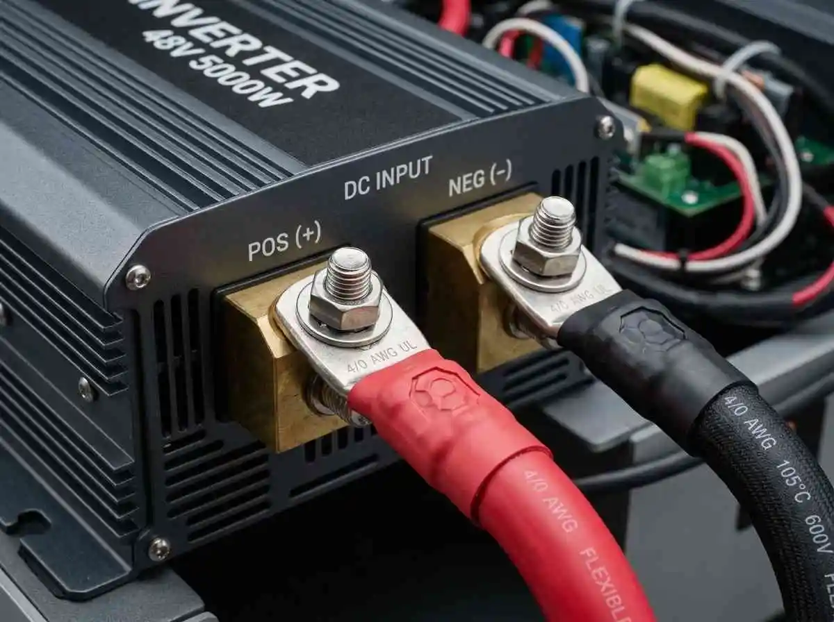
An off-grid battery inverter functions as the electrical heart of a residential power system, transforming low-voltage direct current (DC) from your battery bank into stable 120V/240V alternating current (AC). However, an inverter is only as dependable as the DC cabling feeding its input terminals. Undersized conductors or loose terminal lugs introduce resistance, triggering destructive voltage drops during high-demand motor starts.
When an inductive appliance starts, the instantaneous current pull spikes significantly above continuous nameplate ratings. If your DC conductors drop excessive voltage during this fraction of a second, the inverter’s internal microprocessor senses a false low-battery state and executes an immediate emergency shutdown—even if your lithium cells are sitting at 90% state-of-charge.
Here is the precise mathematical framework for calculating continuous versus surge inverter current, determining DC circular mil cable sizing, and limiting voltage drop below 2% on 48V battery systems.
Continuous vs Surge Amperage: The DC Draw Math
To size battery supply conductors safely, you must convert both continuous alternating current loads and inductive surge spikes back into direct current amperage drawn through the battery cables.
Formula for DC Amperage Draw:
DC Current (Amps) = (AC Power in Watts / Inverter Operating Efficiency) / Inverter Low-Cutoff Voltage (Volts)Never calculate DC cable current using standard nominal battery voltage (48V or 51.2V). Current reaches its absolute maximum when the battery is deeply discharged at its lowest operating threshold (typically 44V DC for a 16S LiFePO4 bank before cutoff).
Practical Sizing Example:
Consider a standard residential 6,000W continuous / 12,000W surge split-phase inverter operating at 92% efficiency:
- Continuous DC Draw:
Continuous Current = (6,000W / 0.92) / 44V = 6,521W / 44V = 148.2 Amps - NEC 125% Continuous Duty Factor:
Required Minimum Ampacity = 148.2A × 1.25 = 185.25 Amps - Instantaneous Surge Draw (Motor Inrush):If an unmitigated well pump cycles on without an electronic soft starter to reduce locked rotor amps, pulling a brief 10,000W surge:
Peak Surge DC Current = (10,000W / 0.88 efficiency under surge) / 44V = 257.5 Amps
Conductors must satisfy the 185.25A continuous thermal baseline while possessing low enough internal resistance to avoid tripping the inverter during a 257A surge spike.
Calculating DC Cable Voltage Drop (The 2% Standard)
While the National Electrical Code permits up to 3% voltage drop across branch circuits, battery-to-inverter DC cabling should strictly target less than 2% (and ideally under 1%). Because 48V systems operate at relatively low voltage compared to utility grids, a drop of just 1.5V DC can breach low-voltage cutoff parameters under heavy inverter loads.
Ohmic Voltage Drop Formula:
Voltage Drop (V) = (2 × One-Way Distance in Feet × Current in Amps × Resistance per 1,000 ft) / 1,000Voltage Drop (%) = (Voltage Drop in Volts / Nominal System Voltage) × 100DC Cable Sizing & Resistance Matrix (NEC Table 310.16)
The table below lists standard fine-stranded, copper battery cable gauges (using high-temperature 90°C/105°C insulation ratings such as UL3239 or welding cable Class K) based on a 10-foot round-trip conductor run (5 feet positive, 5 feet negative):
| Wire Gauge (AWG / kcmil) | Resistance (Ohms / 1,000 ft @ 75°C) | Rated Ampacity (90°C Copper) | Voltage Drop @ 150A Continuous (10 ft) | Voltage Drop @ 250A Surge (10 ft) |
|---|---|---|---|---|
| 2 AWG | 0.190 Ω | 130A (Undersized) | 0.285V (0.59%) | 0.475V (0.98%) |
| 1/0 AWG | 0.120 Ω | 170A | 0.180V (0.37%) | 0.300V (0.62%) |
| 2/0 AWG | 0.096 Ω | 195A | 0.144V (0.30%) | 0.240V (0.50%) |
| 4/0 AWG | 0.060 Ω | 260A | 0.090V (0.18%) | 0.150V (0.31%) |
Verdict for 6 kW Inverters: While 2/0 AWG technically meets continuous thermal requirements, selecting 4/0 AWG pure copper cable reduces total circuit resistance by 37.5%, keeping surge drop down to a negligible 0.15V. This ensures total inverter stability during sudden high-draw inductive spikes audited per our home energy audit guide.
Cable Construction: Why Fine-Stranded Copper is Mandatory
Never install solid-core or coarse-stranded Class B building wire (like standard THHN) between batteries and inverters:
- Vibration and Mechanical Fatigue: Inverter transformers emit a low-frequency 60Hz mechanical vibration. Coarse wire transmits this mechanical vibration into terminal studs, loosening lug connections over time and generating dangerous resistive heat spots.
- Class K / Class M Fine Stranding: High-grade battery cables feature thousands of hair-thin tinned copper strands. This construction provides superior flexibility in tight enclosures while maximizing surface area conductivity.
- Tinned Copper Marine Lugs: Use heavy-duty, seamless closed-end tinned copper eyelet lugs. The tin coating inhibits copper oxidation, while closed-end barrel designs prevent moisture wicking inside the insulation jackets. Always crimp lugs using an 8-ton hydraulic hex-die crimper; mechanical hammer-crimpers leave internal air voids that corrode over multi-year cycles.
Fusing and Upstream Busbar Placement
Every positive DC conductor feeding an inverter must feature fast-acting overcurrent protection placed directly adjacent to the power source. Because high-capacity LiFePO4 batteries deliver dead-short discharge currents in excess of 10,000 Amps, standard automotive breakers will fail to interrupt the arc.
Review our engineering analysis on busbar sizing and Class T vs ANL fuse ratings to guarantee sufficient Interrupting Current Capacity (AIC) before routing DC power through your central disconnects and downstream 16S BMS systems.
Summary
Inverter reliability during emergency grid failures hinges on strict DC circuit sizing. By calculating current draw at minimum low-voltage cutoff thresholds rather than nominal battery voltage, selecting 4/0 AWG fine-stranded tinned copper conductors, and targeting sub-1% voltage drop across all interconnects, you eliminate phantom inverter low-voltage trips and maintain stable household backup power.
1 thought on “Inverter Surge Wattage Math and DC Cable Voltage Drop Calculations (48V Systems)”