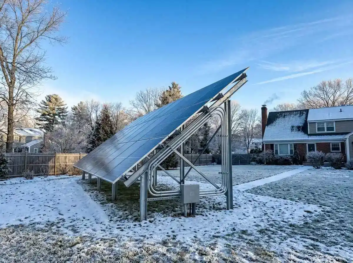
When engineering a residential solar array designed specifically to keep a battery backup bank charged through grid outages, where you mount your photovoltaic (PV) modules dictates total energy harvest. While rooftop installations represent the standard residential choice due to space constraints, ground-mounted arrays offer thermodynamic and geometric advantages that can make or break winter battery autonomy.
A battery storage system does not care about peak summer noon production when the grid is typically stable; it relies on predictable generation during heavy cloud cover, low winter sun angles, and extreme weather. Ground arrays allow homeowners to dial in ideal azimuths, clear snow manually, and bypass complex rooftop life-safety constraints.
Here is the engineering and financial comparison between ground-mount and rooftop solar racking when paired with a 48V home battery system.
Architectural & Electrical Comparison
| Factor | Rooftop Solar Array | Ground-Mounted Solar Array |
|---|---|---|
| Racking & Installation Cost | Lower ($0.30 – $0.55 per Watt) | Higher ($0.75 – $1.20 per Watt due to excavation & concrete) |
| Tilt Angle Optimization | Fixed to roof pitch (Usually 15° to 30°) | Customizable / Seasonal manual adjustment (20° to 60°) |
| Thermal Operating Efficiency | Higher cell temps (Trapped roof heat reduces output by 8–12%) | Superior convective airflow (Cooler operation, higher voltage) |
| NEC 690.12 Rapid Shutdown | Strictly mandatory within 3-ft boundary | Exempt from building boundary rapid shutdown rules |
| Winter Maintenance / Snow Clearing | Dangerous roof ladder access required | Ground-level clearing with soft foam rakes in minutes |
Tilt Angle Optimization Math for Battery Storage
Standard rooftop solar is optimized for maximum annual net metering revenue, typically adopting a tilt equal to the site’s geographical latitude minus 10° to 15° to favor peak summer sun. However, for an emergency battery storage bank, your system design must be optimized for the winter solstice, when sun hours are shortest and utility outages are most frequent.
Winter Tilt Formula:
Optimal Winter Tilt Angle = Local Latitude + 15°If you live at 40° North Latitude (e.g., Denver, CO or Columbus, OH):
- Standard Roof Pitch (4:12 pitch): Produces roughly an 18° tilt angle. At 40°N during December, panels at 18° reflect away significant incident light due to high optical angle of incidence (AOI) losses.
- Ground Mount Winter Optimization:
40° + 15° = 55° Tilt Angle.
Positioning panels at a steep 55° angle perpendicular to the low winter sun increases irradiance capture by over 35% during critical December and January months. Furthermore, a 55° slope causes heavy wet snow to naturally slide off the glass face under gravity.
Operating Temperature & Voltage Behavior
As covered in our technical analysis on DIY solar panel wiring (series vs parallel), photovoltaic cell efficiency drops as temperatures rise, defined by the Temperature Coefficient of Maximum Power (typically -0.35% per °C above 25°C).
Roofs trap rising air underneath the modules, pushing cell temperatures above 65°C (149°F) in moderate weather. Ground-mounted structures benefit from unobstructed, open-air convective cooling on both front and rear surfaces:
- Ground-mounted cells run on average 10°C to 15°C cooler than roof-mounted modules under identical solar irradiance.
- This temperature delta translates to an immediate 4% to 6% boost in active power production, delivering higher charging current directly into your properly sized MPPT charge controller.
Trenching, Conduit Sizing, and Voltage Drop
The primary engineering penalty of ground-mounted solar is physical distance. If your ground array sits 150 to 250 feet away from your utility room, low-voltage wiring will suffer destructive power dissipation.
Minimizing DC Voltage Drop:
Keep voltage drop below 2% between the array and your charge controller:
Voltage Drop (%) = (2 × Distance in Feet × Current in Amps × Resistance per 1,000 ft) / System Voltage × 100The High-Voltage Solution: Instead of running parallel low-voltage strings (e.g., 40V DC at 40A), configure panels in long series strings running at 300V to 500V DC at 10A. High voltage allows the use of standard 10 AWG copper wire over 200 feet while maintaining voltage drop well below 1.5%, saving hundreds of dollars in thick trench copper conductors.
Remember that all exterior conductors must pass through schedule 40 or 80 PVC conduit buried to NEC minimum trench depths (typically 18 inches below grade), terminating into a robust external solar DC disconnect switch before entering the home.
Summary
If you have adequate land unshaded by trees, a ground-mounted solar array delivers unmatched reliability for residential battery backup systems. The ability to lock in steep winter tilt angles (Latitude + 15°), shed snow naturally, operate 12°C cooler, and clear panels without climbing onto frozen shingles far outweighs higher initial trenching costs when grid resilience is your primary objective.