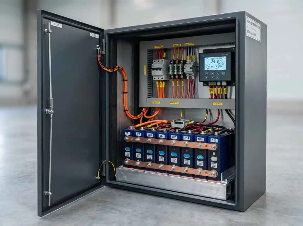
While Lithium Iron Phosphate (LiFePO4) chemistry offers exceptional cycle life and thermal stability, it possesses one critical electrochemical vulnerability: an absolute intolerance to charging at or below freezing temperatures (0°C / 32°F). While discharging remains chemically viable down to -20°C (-4°F) with moderate capacity derating, forcing charge current into frozen cells induces catastrophic, irreversible lithium metal plating on the graphite anode.
Left unmitigated, lithium plating degrades total storage capacity, triggers internal micro-short circuits, and permanently voids manufacturer warranties. For homeowners housing energy storage systems in unconditioned garages, outbuildings, or exterior sheds, an active thermal management strategy is mandatory.
Here is the engineering methodology for calculating enclosure thermal resistance (R-value), sizing DC silicone heating pads, and automating thermal cutoff controls for a 48V residential battery bank.
The Electrochemistry of Low-Temperature Charging
During normal ambient charging, lithium ions migrate smoothly through the liquid electrolyte and intercalate into the layered graphite anode lattice. As internal core temperatures drop below freezing:
- Electrolyte Viscosity Increases: The liquid electrolyte thickens, sharply impeding ion mobility.
- Internal Cell Resistance Spikes: Cell impedance increases by 200% to 400%, generating localized voltage spikes during charge acceptance.
- Plating vs Intercalation: Incoming lithium ions cannot penetrate the stiff graphite matrix fast enough. Instead of intercalating safely, ions deposit on the anode surface as metallic lithium dendrites, creating sharp physical needles that risk puncturing the microscopic separator.
As established in our technical guide on choosing and sizing a 16S BMS, a digital BMS low-temp sensor prevents incoming current below 2°C (35.6°F). However, shutting down charging leaves your array idle. Active thermal heating keeps the cells receptive to solar energy throughout sub-zero winters.
Enclosure Thermal Loss: Calculating Required Wattage
Heating an uninsulated metal box exposed to freezing winds drains excessive battery energy. To size heating elements accurately, you must first calculate heat loss through the enclosure walls using standard thermodynamic heat transfer principles.
Heat Transfer Formula:
Required Heating Power (Watts) = (Surface Area in sq ft × Temperature Delta in °F) / (R-Value × 3.412)Real-World Sizing Example:
Consider a DIY 48V 280Ah battery bank housed in an insulated plywood enclosure:
- Total Enclosure Surface Area: 22 sq ft
- Insulation: 1-inch rigid Polyisocyanurate (Polyiso) foam board with an R-value of R-6.5
- Design Ambient Low: 0°F (-17.7°C)
- Target Internal Core Temperature: 45°F (7.2°C) (Safe baseline for 0.5C charge acceptance)
- Temperature Delta ($\Delta T$):
45°F - 0°F = 45°F
Calculation:
Required Watts = (22 sq ft × 45°F) / (6.5 × 3.412) = 990 / 22.18 = 44.6 WattsEngineering Rule of Thumb: Apply a 1.5× safety margin to account for corner thermal bridging and door gasket infiltration. A continuous thermal heat source of 65W to 75W maintains the enclosure at safe operating temperatures even during severe winter storms.
Quick Heating Pad Sizing Matrix (48V LiFePO4 Banks)
| Battery Capacity | Typical Enclosure Size | Insulation Type | Recommended Heating Power | Daily Energy Consumption |
|---|---|---|---|---|
| 48V 100Ah (5.1 kWh) | Compact Box (~12 sq ft) | 0.75″ XPS Foam (R-3.8) | 30W – 40W | ~0.7 to 0.9 kWh/day |
| 48V 280Ah (14.3 kWh) | Standard Cabinet (~22 sq ft) | 1.0″ Polyiso (R-6.5) | 60W – 75W | ~1.4 to 1.8 kWh/day |
| 48V 560Ah (28.6 kWh) | Dual-Stack Rack (~38 sq ft) | 1.5″ Polyiso (R-9.8) | 100W – 120W | ~2.4 to 2.8 kWh/day |
Hardware Selection: Silicone Heating Pads vs Convection Air Heaters
Never place high-temperature incandescent bulbs or exposed ceramic space heaters directly beside lithium cells. Uneven localized thermal hotspots degrade outer cells while inner cells remain cold.
1. Flexible Silicone Heating Pads (Bottom-Mount with Heat Spreaders)
Industrial low-watt density silicone heating pads (rated for 12V or 24V DC) provide the most reliable heat transfer.
Critical Rule: Never place heating pads in direct contact with the thin aluminum or blue PET wrap of prismatic LiFePO4 cells. Always mount the pads underneath an aluminum heat-diffuser plate (minimum 1/8-inch thickness). The aluminum plate distributes heat evenly across the base of all 16 cells, preventing localized thermal stress.
2. Digital Dual-Stage Thermostat Controllers
Automate power delivery using an independent digital controller (such as an Inkbird DC temperature relay):
- Heater ON Threshold: Programmed to engage when core cell probes drop below 5°C (41°F).
- Heater OFF Threshold: Programmed to disengage once core sensors climb above 10°C (50°F).
Power Sourcing and Upstream Circuit Integration
Powering your heating pads directly from the battery bank during prolonged outages requires accounting for parasitic winter consumption. When performing calculations under our home energy audit and vampire load framework, add 1.5 kWh/day of dedicated thermal overhead to your baseline reserve.
Ensure that all DC auxiliary heating branch circuits tap into your distribution busbar through dedicated, properly sized fuse blocks. Review our specifications for busbar sizing and fuse selection to ensure small gauge auxiliary wiring remains protected from high-capacity short circuit hazards.
Summary
Protecting a residential LiFePO4 battery bank against sub-zero degradation requires a dual-layered defense: configuring hard low-temperature charging cutoffs inside the BMS while deploying an insulated enclosure paired with thermostatic silicone heating pads. Sizing for approximately 60W to 75W of diffused bottom heating ensures your energy storage bank remains fully functional and receptive to solar harvest year-round.