A common misconception among homeowners installing residential battery backup systems is that solar array shading behaves proportionally: if 10% of a photovoltaic module is covered by a tree branch or chimney shadow, the system loses 10% of its power output. In real-world electrical physics, even a tiny sliver of hard shade across a single solar cell can throttle an entire series string’s output by 50% to 80% while creating dangerous localized heat traps known as thermal hotspots.
Because solar cells within a standard monocrystalline module are wired in series, current flow behaves like water running through a single garden pipe. A single shaded cell acts as a high-resistance bottleneck, restricting current for every unshaded cell upstream and downstream.
Here is the underlying electrical mathematics of partial shading, the semiconductor physics of bypass diodes, and how to protect your energy storage system from unharvested winter watts and module degradation.
The Physics of a Shaded Solar Cell: The Reverse Bias Phenomenon
Under uniform sunlight, every photovoltaic cell generates approximately 0.5V to 0.6V DC while conducting full short-circuit current ($I_{sc}$). When light is physically blocked from a single cell:
- Photocurrent Collapses: The shaded cell ceases generating electrons, dropping its internal current generation to near zero.
- Forced Current Conduction: Because the surrounding unshaded cells continue pushing high current through the series loop, they force the shaded cell into Reverse Bias.
- Power Dissipation (Hotspots): Instead of acting as a power source, the reverse-biased cell transforms into an electrical resistor, dissipating the energy produced by surrounding cells as intense localized heat. Temperatures can rapidly exceed 150°C (302°F), melting internal EVA laminates, cracking protective front glass, and permanently ruining cell efficiency.
How Bypass Diodes Protect the Module
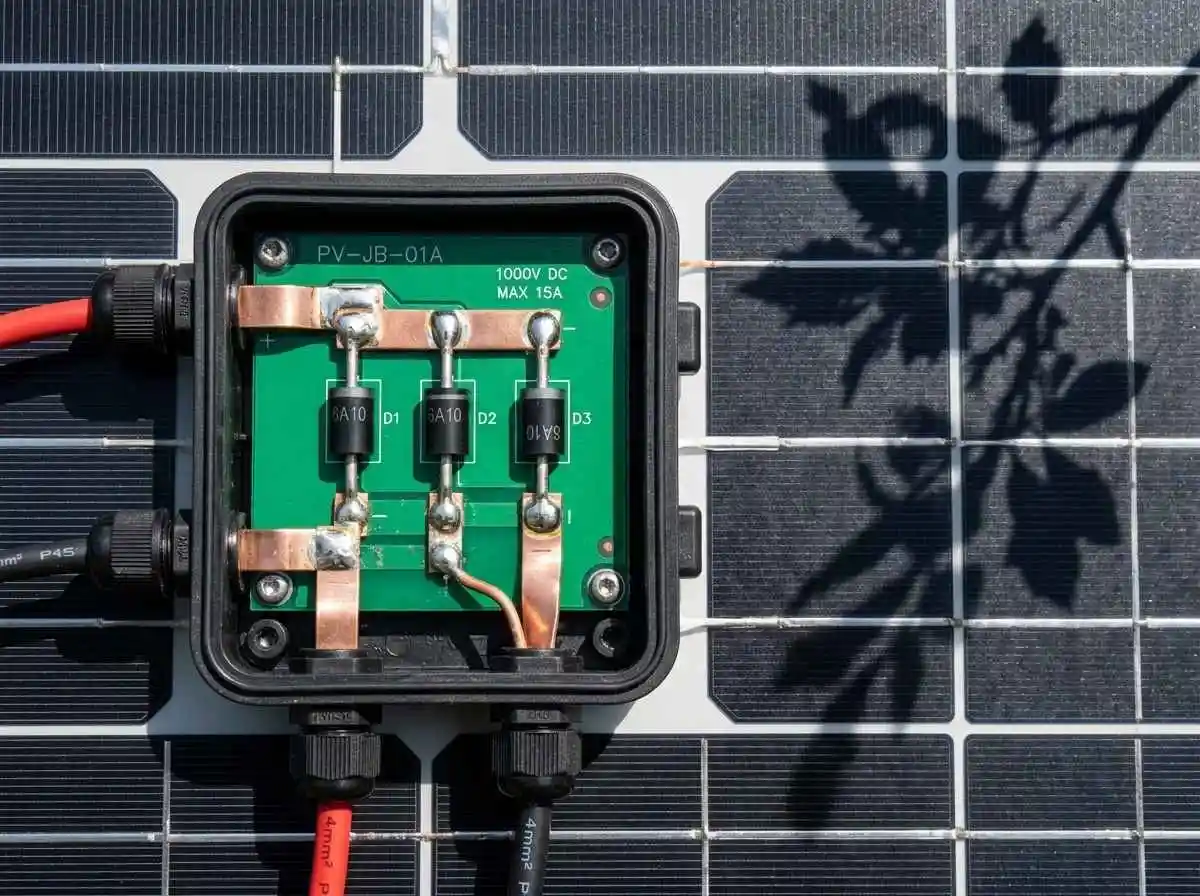
To prevent destructive reverse-bias runaway, solar panel manufacturers incorporate bypass diodes inside the weather-sealed junction box on the rear of the panel.
Standard 60-cell or 72-cell residential panels are internally partitioned into three distinct vertical sub-strings, with one semiconductor diode wired in anti-parallel across each group (typically 20 to 24 cells per diode):
| Operating Condition | Diode State | Current Path | String Voltage Impact |
|---|---|---|---|
| Full Uniform Sun | Reverse Biased (OFF / Closed) | Flows normally through all 60 cells in series | 100% Full Rated Voltage (~36V–40V Vmp) |
| Single Cell Shaded | Forward Biased (ON / Conducting) | Bypasses the shaded 20-cell group via diode | Voltage drops by precisely 33.3% (~12V lost) |
| Two Groups Shaded | Two Diodes Conducting | Bypasses 40 cells; routes through remaining 20 | Voltage drops by 66.6% (~24V lost) |
When a cell becomes shaded, the voltage across that cell group goes negative. Once this negative potential exceeds the forward threshold voltage of the silicon diode (typically ~0.7V), the diode turns ON, conducting current safely around the shaded group. This halts heat buildup but sacrifices that section’s energy generation.
Partial Shading Mathematics: The MPPT Curve Dilemma
When bypass diodes activate, they radically warp the array’s Current-Voltage (I-V) and Power-Voltage (P-V) curves. Instead of a single clean bell curve with one clear Maximum Power Point (MPP), the controller sees a distorted curve containing multiple local power peaks.
Mathematical Example of Shading Impact:
Consider a series string of six 400W solar modules feeding a 48V battery bank via a high-voltage charge controller. Each module operates at 40V $V_{mp}$ and 10A $I_{mp}$:
Total Unshaded Output = 6 panels × 400W = 2,400 Watts (240V @ 10A)Now, suppose a tree shadow covers just two cells on a single panel, triggering one bypass diode:
- The active string loses one-third of that panel’s potential:
40V / 3 = 13.3 Volts lost. - New String Working Voltage:
240V - 13.3V = 226.7 Volts. - Remaining Module Current: 10 Amps.
- Delivered Array Output:
226.7V × 10A = 2,267 Watts(A manageable 5.5% system loss).
The Catastrophic Scenario (Diode Failure to Activate):
If the charge controller fails to sweep voltage wide enough to trigger the diode, the entire string is forced to throttle current down to the shaded cell’s restricted flow (~2 Amps):
Throttled Array Output = 240V × 2A = 480 Watts (An 80% system collapse!)This is why proper pairing with an advanced tracking algorithm, as detailed in our guide on sizing MPPT charge controllers and managing input limits, is essential for shaded roofs.
Engineering Solutions for Shaded Battery Arrays
If your property features unavoidable morning or afternoon shade, implement these hardware architectures:
1. Half-Cut (Split-Cell) Solar Modules
Modern split-cell modules divide traditional 6-inch silicon wafers into two equal halves. Instead of three series sub-strings, half-cut panels feature six parallel sub-strings with center-mounted bypass diodes. If the bottom half of the panel is covered in snow or shade, the upper half continues generating full rated output independently.
2. Parallel String Wiring Strategy
Review our engineering blueprint on DIY solar panel wiring (series vs parallel). In heavily shaded micro-climates, designing dual parallel strings prevents a single shaded module from dragging down the entire array’s operational voltage.
3. Module-Level DC Optimizers (MLPE)
Installing DC optimizers (such as Tigo or SolarEdge modules) directly behind shaded panels dynamically adjusts voltage and current at the individual panel level. This allows unshaded panels in the string to produce full power at 10A while stepping down the shaded panel’s output to match the string’s current without forcing diode conduction.
Furthermore, deploying MLPE hardware satisfies rapid shutdown mandates outlined in our guide on solar DC isolators and NEC 690 safety rules.
Summary
Partial shading introduces nonlinear power collapse and severe thermal degradation if left unaddressed. By selecting split-cell modules with high-grade Schottky bypass diodes, ensuring your MPPT charge controller utilizes full-curve sweeping algorithms, and optimizing physical mounting tilt per our ground mount vs rooftop solar guide, you maintain maximum charge delivery to your 48V battery bank through challenging weather conditions.